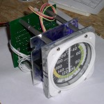
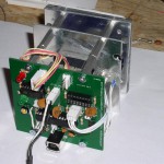
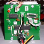
I completed the build of my ASI (air speed indicator) for my flight simulator project. There were some minor issues with the PCB but nothing a few jumper wires couldn’t fix. The most frustrating “bug” was with the USB connector. For some reason the connectors I ordered have an unconnected ground pin. Ground is instead connected to the case or shield of the connector. Once I added a jumper from the connector case to the ground pin everything worked great.
You may have noticed an empty IC socket and unused connectors on the PCB. That is because I designed the board to support two stepper motors, two limit switches, two encoders and a switch but the ASI only uses one stepper and one limit switch.
Time to build instrument number 2!


Hi, Nice work… Where did you get the white plastic ring that covers the faceplate?
The nice faceplate was made by MyCockpit forum member Tripacer. Here is the forum thread that follows my progress of building the ASI: http://www.mycockpit.org/forums/showthread.php/14873-Asi
Thatís some nice work you have there. Itís about time I got my project off the ground, so if you do decide to supply kits please drop me an email.
Thanks Bill. If I did offer kits it would be only the USB controller circuit as the mechanical design is from Mike Powell’s excellent book “Building Simulated Aircraft Instrumentation”. There is quite a pile of PCBs so I may offer bare boards and/or ready to go controllers at some point.
http://www.mikesflightdeck.com/mfdbooks.htm
Greetings friend, I would build some analog instruments for my simulator, I wonder if you have the schematics and board layout to provide or even sell, grateful for the attention.