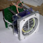
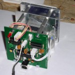
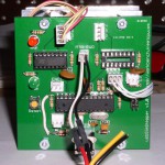
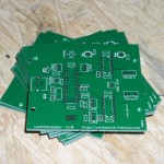
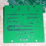
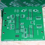
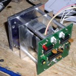
I completed the build of my ASI (air speed indicator) for my flight simulator project. There were some minor issues with the PCB but nothing a few jumper wires couldn’t fix. The most frustrating “bug” was with the USB connector. For some reason the connectors I ordered have an unconnected ground pin. Ground is instead connected to the case or shield of the connector. Once I added a jumper from the connector case to the ground pin everything worked great.
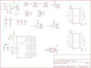
You may have noticed an empty IC socket and unused connectors on the PCB. That is because I designed the board to support two stepper motors, two limit switches, two encoders and a switch but the ASI only uses one stepper and one limit switch.
Time to build instrument number 2!
