AVR Programmer (old)
A better design was found, that is what I use now.
I am designing a circuit board for a simple stk200 style programmer that will work with the uisp programming software for Linux. This programmer will work with most 8, 20 or 40 pin AVR chips.
| Schematic | Component Layout | ||||||||||||||||
|---|---|---|---|---|---|---|---|---|---|---|---|---|---|---|---|---|---|
 |
 |
||||||||||||||||
| 6-pin ISP Header | 10-pin ISP Header | ||||||||||||||||
|
|
||||||||||||||||
Updates
November 9, 2005
Breadboarded and tested the circuit
 |
Note that there is an exta IC in the picture. I did not have a 244 on hand so I used to 245 and a 4049 (inverter) to make a 244. |
November 19, 2005
Built circuit inside small project box.
 |
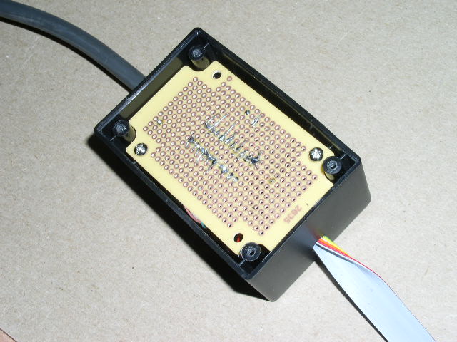 |
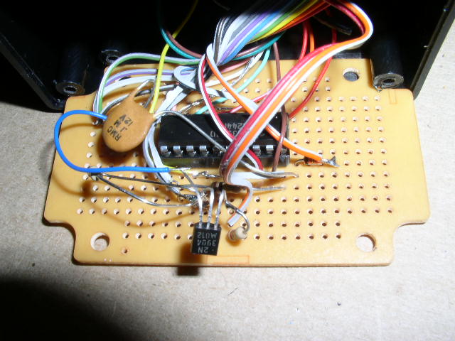 |
|
Note: My cable from the PC is rather long so I added a 0.1uF capacitor between Vcc and Gnd on the 244. I also observed that with the LED driven directly from pins 12/14 I would get flash verify errors. Adding a transistor drive eliminated this problem.
December 23, 2005
I have seen some problems with this programmer. Uploading flash caused 2 ATMega16’s and an ATTiny26 to stop responding. I was able to revive the ATTiny26 by hooking the calibration output of my scope to XTAL1 and using a dasa style programmer to erase the chip. The ATMega16’s are still quite dead. I think the issue is the length of my cable.
The dasa style programming cable uses 4 wires from the serial port (RESET=RTS SCK=DTR MOSI=TXD MISO=CTS). Like many others on the internet I have to manually reset the chip between operations. I leave the RTS line unhooked and just use 3 of the 4 wires.
December 31, 2005
I was able to revive the ATMega16’s by applying a 1MHz clock signal to the XTAL1 pin and resetting the fuse bits to default with my serial programmer. The clock signal was generated with another AVR running a simple pin toggling infinite loop.