Archive for the ‘AVR’ Category

A Nav/Com radio for the cockpit

Saturday, February 20th, 2010

Unlike the wide body boys there do not seem to be any affordable options for us general aviation simmers when it comes to the radio stack. Sure there are some fantastic products out there, the SimKits line for instance, but they are priced higher than the Chief of Finance will allow. There are also some cheaper alternatives but in my opinion they sacrifice too much in realism. So, like my instruments, I decided to build my own.

I am starting with a nav/com unit based on the Bendix King KX165 like the image above. The biggest obstacle was finding a suitable display that wouldn’t break the bank. After a lot of searching I came across a 4 digit 7-segment display at Futurlec that was priced reasonably and the correct size. Using the dimensions provided at Futurlec I mocked up a display. While the spacing is tighter than the real thing I think it is close enough for my purposes.


With the display picked out and on order I worked on a face plate design. I am thinking about using 1/8″ plexi covered with a printed label. Here is my CAD design.


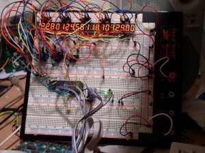
For the most flexibility I decided to build a microcontroller based circuit to communicate with the host PC and control the display. Like my instruments this nav/com unit will connect via USB and be controlled by my usbSimCentral program. I proved out my display driving circuit on a breadboard because I was concerned about being able to refresh 20 digits quickly enough. It works fine with no flicker.


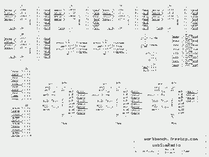
Here is the schematic for the display board. This includes the 7-segment displays and shift registers as well as the encoders and buttons.


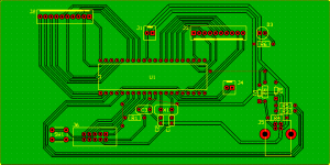
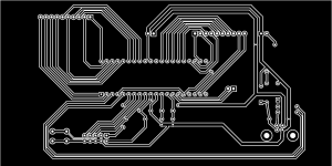
The PCB design is a little more complicated than needed because I am etching a single sided version with jumper wires for the prototype. If there is enough interest I plan to sell a kit version and will have boards professionally made for that.

The next step is to etch the two boards. I also need to order a few parts as I do not have the surface mount shift registers or encoders. This is a work in progress, stay tuned for updates.

Garage Parking Assistant

Friday, January 1st, 2010

In true geek style I went overboard in fulfilling this long over due honey-do list item. It is a tight fit for our minivan in our “oversize” garage after I added storage shelves to the front wall. The wife has wanted some way to know when she is pulled in far enough for some time and I had been putting it off. An article in the latest issue of Nuts and Volts inspired me to finally do something about it.

Enter my version of the Garage Parking Assistant.

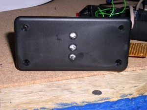
This is the face of the main unit, which consists of 3 lights (high intensity LEDs) in traffic signal style of red, yellow, and green.

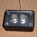
It works by measuring how far your vehicle is from the wall via this ultrasonic range finder. With no vehicle in all lights are off. As you enter the garage the Approach light (green) turns on. When you get near the stopping area the Slow light (Yellow) turns on and when in position the Stop light (red) then lights. If you go too far in the red light flashes at you to back up. If no distance change is detected for 2 minutes then all LEDs go dark to save power and LED life. Calibration is done by holding down the button for more than 2 seconds, which enables a programming mode. Each light is activated in turn and you push the button when the vehicle is at the desired distance. I have not yet mounted this in the garage but work shop tests have been successful. The unit is installed and has been working perfectly for several weeks. The wife approval factor is high.

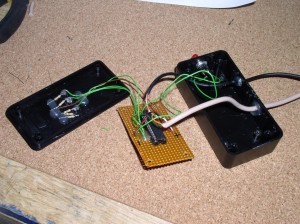
The circuit is simple enough that I have not yet drawn a schematic. It consists of an AVR ATmega8, SRF04 range finder, 3 LEDs with resistors, and a push button. Two Radio Shack boxes house the main unit and range finder and the whole thing is powered by an old phone charger that puts out a reasonably filtered 5VDC.


AVR GCC code

ASI build complete

Tuesday, December 15th, 2009

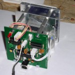
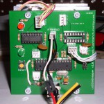
I completed the build of my ASI (air speed indicator) for my flight simulator project. There were some minor issues with the PCB but nothing a few jumper wires couldn’t fix. The most frustrating “bug” was with the USB connector. For some reason the connectors I ordered have an unconnected ground pin. Ground is instead connected to the case or shield of the connector. Once I added a jumper from the connector case to the ground pin everything worked great.

ASI_pcb04 ASI_pcb03 ASI_pcb02

You may have noticed an empty IC socket and unused connectors on the PCB. That is because I designed the board to support two stepper motors, two limit switches, two encoders and a switch but the ASI only uses one stepper and one limit switch.

Time to build instrument number 2!

usbSimStepper PCBs have arrived

Tuesday, October 27th, 2009

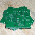
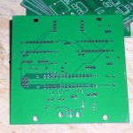
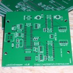
I designed a dual stepper motor controller that interfaces to a computer via USB for use in my flight simulator. These boards will drive various instruments, such as my airspeed indicator. This is the first time I have used Seeed Studio for PCBs and I am very please so far with the end result. The total cost was right at $50 for 11 of these boards which measure about 3 inches square.

usbSimStepper01 usbSimStepper02 usbSimStepper03


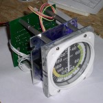
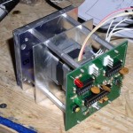
Here is one of the boards mostly populated with parts and installed on my home made airspeed indicator.

ASI_pcb01


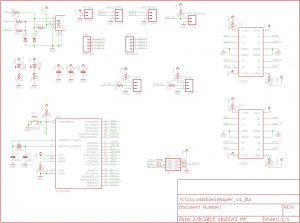
Update: There were a couple of minor errors on the board layout. Here is an updated schematic.