I received a nice little JVC stereo (Model CA-HXZ3) that someone had left behind as trash in an apartment that my parents manage. It has a 3 CD changer, tape deck, AM/FM stereo and an auxiliary input. One of the buttons on the front hints at CD recording capability. With all this geeky goodness I just had to have it. =)
When plugged in the unit immediately powers on and goes through what looks like a normal startup routine with a lot of flashing lights and beeps. Unfortunately the only sound it made was the beeps, nothing came from the main speaker outputs. I also noticed that the power button and the CD eject buttons did not seem to do anything.
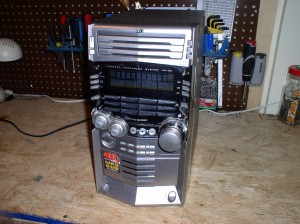
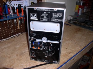
I finally took the time to tear into it this weekend and took some pictures along the way.
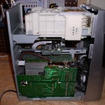
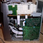
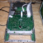
Here we have a view of each side of the unit as well as the front panel by itself in the picture on the right.
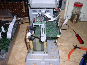
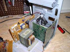
There are boards surrounding a massive transformer and a large aluminum heat sink, both cooled by a fan in the rear. I checked all of the fuses on the power board and they tested good. There were no obvious trouble signs until I removed the large board on top.
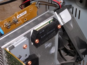
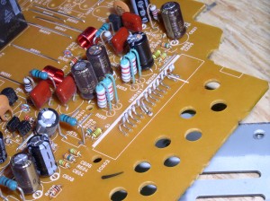
That power amp IC on the left is supposed to be connected to the pins in the picture on the right. The top board lifted right off with no effort so all of those pins had been knocked loose. This thing appears to have been dropped. Hard!
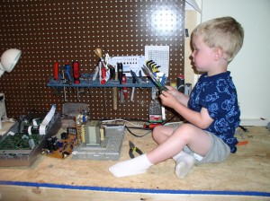
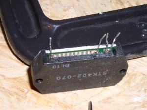
By this time I gave in to the persistent “Daddy, up!” coming from Maddox and let him play on the workbench for a while. An attempt to re solder the pins led only to frustration. There is not enough room to do a good soldering job so I gave up. Luckily this is a common part and $10 via PayPal later I have one on the way from an eBay store. With that part ordered I continued to check the rest of the system for obvious damage.
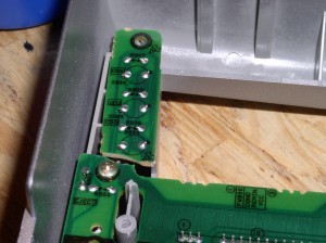
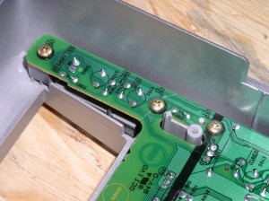
The break on the left was readily apparent and you can just make out the crack by the middle screw in the pic on the right. These two tabs house the unresponsive power and CD eject buttons.
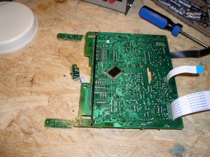
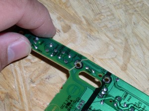
I removed this board from the front panel in preparation for repair. A test fit showed an easily glueable clean break. Repairing the traces will be easy but time consuming. I think my first attempt will be to clean the copper on either side of the crack and attempt a short bridge. If that doesn’t work out I will run small diameter wire from the nearest pads.
This concludes part 1. I have glued the two tabs back in place and am waiting on the replacement IC. While I am waiting I will work on getting the cracked traces repaired.
Update
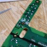
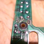
I cleaned up the broken trace ends with the point of a small round needle file and then with much squinting and soldering managed to repair all the traces on both broken pieces. If my repairs survive reassembly of the unit then I am in good shape. The closeup picture is kind of a mess, I was experimenting with the macro mode of my camera. It is the best closeup shot I could get of the tiny traces.
