Archive for the ‘Electronics’ Category

Joystick controller

Monday, January 26th, 2009

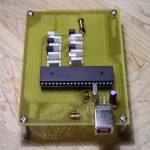
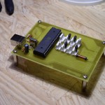
This weekend I etched a board for the excellent MJoy16-C1 controller board that I have mentioned in the past. This board is a USB joystick on steroids, supporting up to 8 axis, 64 push buttons, 16 toggle switches and a POV hat. The creator (Mindaugas Milasauskas) seems to have dropped from the net and the old domain is now a search farm. There is one website selling these online for the tidy sum of 199EUR. I found a good mirror of the old project page and downloaded the docs and hex file there. Update: This mirror is now gone as well. 🙁

mjoy16-002 mjoy16-005

mjoy16-009

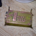
I have had good luck using the toner transfer method of etching PCBs. Google it for a lot of sites with step by step details on the method. This etch wasn’t the cleanest I have done (I forgot to use photo paper and used regular printer paper), but was functional. I didn’t bother populating the parts for the ISP port, hence the blank area beside the USB connector. The jumpers on the white headers prevent false readings from unconnected axis. I had all the parts on hand with the exception of a 40-pin header for the digital inputs. Now I am one step closer to a functional panel.
Designing a better PCB

Tuesday, November 18th, 2008

A tutorial from SparkFun.

http://www.sparkfun.com/commerce/tutorial_info.php?tutorials_id=115

Viewsonic VP140 repair

Monday, November 10th, 2008

I received a Viewsonic VP140 LCD monitor for free, but it did not work. Pushing the power button resulted in nothing happening. About an hour of tinkering and tracing circuits led me to suspect two electrolytic capacitors on what I will call the switched 12V power circuit. There was a F7304 power mosfet IC that seemed to feed a 12V bus that powered the main part of the circuit. This IC was getting good power and seemed to want to turn on but there was only the briefest flicker of voltage turning on when pushing the power button. There are two caps on the downstream side of this IC, C24 and C110 (I think, need to take pictures for this posting). I unsoldered these two caps and was rewarded with a green power light when pushing the power button. I replaced the two caps, buttoned back up and now have a functioning LCD monitor.

For anyone with a similar monitor be aware that there are several different PCB styles for this monitor. Mine is the 300 series (need picture of PCB here).

PCB service

Sunday, November 9th, 2008

Futurlec has some really cheap prices on PCB manufacturing. I might have to try them out for my next project.

Futurlec PCB Service